An Ultrasonic Welding Mold for Electronics is a critical tooling component in the ultrasonic plastic welding process. It determines how ultrasonic vibration and welding pressure are transferred to the plastic assembly, directly affecting joint consistency, dimensional accuracy, surface appearance, and production yield. In electronics manufacturing, where components can be small and geometries are often complex, the mold cannot be treated as a generic accessory to the ultrasonic welding machine.
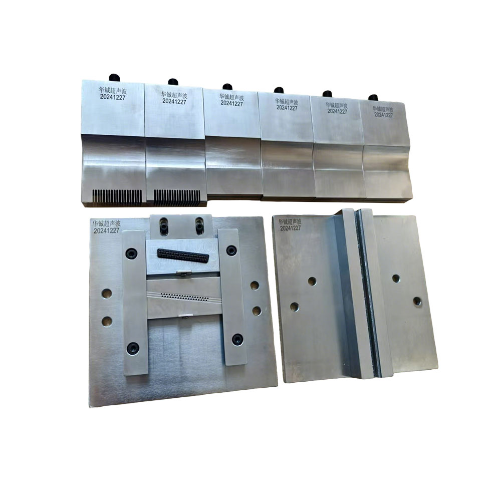
A suitable Ultrasonic Welding Mold for Electronics must be developed around the actual plastic material, joint geometry, component dimensions, welding frequency, amplitude, pressure, and required cycle time. When these parameters are properly matched, ultrasonic energy can be concentrated at the intended welding interface instead of being unnecessarily transmitted into sensitive areas of the component.
Why Mold Design Determines Welding Quality
Ultrasonic welding converts high-frequency mechanical vibration into localized heat through friction and material deformation at the joint interface. The mold, or tooling system, controls how this mechanical energy reaches the workpiece.
If the contact surface does not properly match the component geometry, the workpiece may move during welding or receive uneven pressure. This can produce incomplete bonding in one area and excessive melting in another. For electronics housings, connectors, sensor components, switches, and other precision plastic parts, these variations can lead to cosmetic defects or dimensional changes that affect subsequent assembly.
The mold therefore needs to provide stable positioning and repeatable force transmission. The contact geometry should follow the actual component rather than relying on a simple flat support surface.
Match the Mold to the Welding Frequency
Ultrasonic welding systems commonly operate at frequencies such as 15 kHz, 20 kHz, 28 kHz, 35 kHz, and 40 kHz. Frequency selection influences the characteristics of the vibration system and must be considered when developing the corresponding tooling.
Lower-frequency systems are generally associated with higher vibration amplitude and can be suitable for larger or more demanding plastic components. Higher-frequency systems can be advantageous for smaller components and applications where more localized energy delivery is required.
The mold itself does not independently determine the welding frequency, but its geometry and mass must be compatible with the ultrasonic system. A tooling design developed for one frequency should not automatically be transferred to another machine without checking the vibration characteristics and mechanical interface.
For electronics applications, this becomes particularly important when switching between compact connector housings, larger enclosures, and thin-wall components.
Plastic Material Changes the Welding Window
Different thermoplastics respond differently to ultrasonic vibration. Common engineering plastics used in electronics can have different melting temperatures, stiffness, crystallinity, moisture sensitivity, and energy-transfer characteristics.
Amorphous materials such as ABS and PC/ABS may behave differently during welding from semi-crystalline materials such as PA, PBT, or PP. Material combinations also matter when two different plastics are being joined.
The welding mold should therefore be designed around the actual material combination rather than simply the external dimensions of the component. The horn and fixture need to work together to concentrate energy at the joint while keeping surrounding features stable.
For production development, parameters such as amplitude, welding pressure, trigger force, weld time, hold time, and energy should be optimized through actual samples. The mold should provide a repeatable mechanical foundation for this process window.
Joint Geometry Is a Key Design Input
An electronics housing may use an energy director, shear joint, step joint, or another specially designed interface. The tooling must allow the ultrasonic energy to reach the intended welding zone.
An energy director concentrates contact stress into a small area, helping initiate localized melting. If the fixture allows the housing to deform away from the joint, however, part of the ultrasonic energy can be lost through unwanted movement.
The support surface should therefore provide sufficient contact around the welding area while avoiding interference with bosses, terminals, PCB components, cable outlets, clips, and other features.
This is particularly important for electronic assemblies with irregular three-dimensional shapes. A fixture that supports only the external outline may not provide sufficient stability around the actual weld line.
Dimensional Accuracy Affects Repeatability
Electronics components often require tighter dimensional control than general plastic products. The ultrasonic welding mold should maintain a consistent relationship between the part, horn, and welding interface throughout repeated cycles.
Critical dimensions may include locating-pin positions, cavity dimensions, support heights, contact surfaces, alignment features, and the relationship between the mold and machine tooling interface.
If the fixture is machined inconsistently, the welding position can shift from one component to another. Even a small positional deviation may become significant when the weld is close to a connector terminal, PCB edge, sealing surface, or precision assembly feature.
For high-volume production, machining accuracy and inspection should therefore be considered part of the tooling specification rather than secondary manufacturing details.
Tooling Material and Surface Treatment Matter
The mold material needs to provide sufficient strength, dimensional stability, and wear resistance for the expected production cycle. Aluminum alloys can be useful for lightweight tooling and rapid machining, while steel or other harder materials may be selected when higher wear resistance or longer production life is required.
Material selection should reflect production volume and component characteristics. A prototype mold used for process validation does not necessarily require the same construction strategy as tooling expected to operate continuously in mass production.
Surface treatment can also be considered where the mold contacts plastic components repeatedly. The objective is to maintain stable contact and reduce wear without creating marks on visible surfaces.
Mold and Horn Must Be Developed as a System
A common source of welding problems is treating the ultrasonic horn and mold as independent components. In reality, the horn transfers vibration into the upper component while the mold supports the lower component and controls its movement.
If the horn applies force to a thin or unsupported area, the part can deform before the joint reaches the required welding condition. If the mold is excessively rigid in the wrong location, stress can instead concentrate in areas that were not intended to receive ultrasonic energy.
Effective tooling design therefore requires coordination between the horn contact surface, part geometry, fixture support, welding line, and machine parameters.
This system-level approach is especially useful for electronics products containing delicate internal components. The tooling should stabilize the plastic shell without transferring unnecessary mechanical stress into PCB assemblies or sensitive inserts.
Applications in Electronics Manufacturing
An Ultrasonic Welding Mold for Electronics can be designed for a wide range of plastic components, including electronic housings, connectors, sensors, switches, small appliance components, battery-related plastic structures, and other precision molded parts.
For a small connector housing, the priority may be accurate positioning and protection of terminals. For a larger electronic enclosure, the tooling may need to distribute clamping force across a longer weld line. For sensor components, maintaining alignment and preventing deformation can be more important than simply achieving the shortest cycle time.
The tooling concept should therefore be developed from the component's actual failure risks rather than from a standardized mold shape.
Why Custom Tooling Capability Matters
Standard ultrasonic molds may be suitable for simple geometries, but electronics manufacturing frequently involves customized housings, complex joint profiles, inserts, internal structures, and tight dimensional requirements. A custom Ultrasonic Welding Mold for Electronics can be designed around the exact component and production process.
Huacheng integrates technology R&D, manufacturing, sales service, and customized solutions in the plastic welding equipment field. Its product portfolio includes ultrasonic plastic welding machines operating at 15 kHz, 20 kHz, 28 kHz, 35 kHz, and 40 kHz, as well as ultrasonic molds, hot-melt welding machines, hot-melt molds, equipment maintenance, and ultrasonic welding processing services.
This combination allows tooling development to be considered alongside the ultrasonic welding equipment and process parameters. For new electronic components, the workflow can begin with the plastic material, weld structure, component dimensions, required production volume, and target welding performance before determining the appropriate tooling configuration.
The right Ultrasonic Welding Mold for Electronics should ultimately provide more than dimensional compatibility with a machine. It should deliver stable part positioning, controlled energy transfer, repeatable pressure distribution, and reliable access to the intended weld interface. When mold geometry, welding frequency, plastic material, joint design, and process parameters are developed as one system, manufacturers can achieve more consistent welding results while reducing defects and unnecessary tooling adjustments during production.
www.sonicweldtech.com
Shenzhen Huacheng Ultrasonic Equipment Co., Ltd.
About Author

More Stories
Hydraulic Press Solutions for Four Key Manufacturing Industries
Water Hammer in HVAC Hydronic Systems: Causes and Prevention
PE Pipe Extrusion Line for Embedded Copper Wire Production