The transition toward autonomous mobility is fundamentally reshaping vehicle architecture. At the center of this transformation lies Next-Gen Drive-By-Wire Technology, a fully electronic control system that replaces traditional mechanical linkages with high-precision electronic actuation.
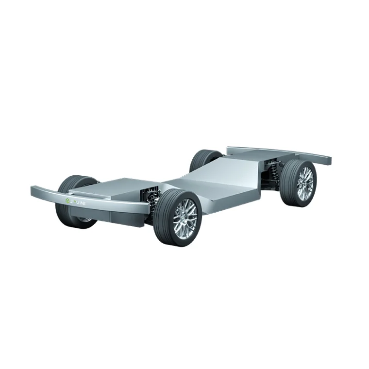
Unlike conventional steering, braking, and throttle systems that rely on mechanical cables, hydraulic pressure, or direct physical coupling, drive-by-wire systems operate through sensor-actuator-control loop architecture, enabling millisecond-level response, modular chassis design, and software-defined vehicle behavior.
For applications such as autonomous logistics, unmanned delivery vehicles, industrial inspection robots, and special-purpose autonomous platforms, drive-by-wire is not an upgrade—it is the foundational control layer.
1. System Architecture of Next-Gen Drive-By-Wire Technology
A complete drive-by-wire system is composed of four tightly integrated subsystems:
-
Input sensing layer (steering, braking, acceleration intent detection)
-
Central control ECU (real-time decision and signal processing)
-
Actuation system (electromechanical steering, braking, and throttle units)
-
Safety redundancy layer (fail-operational architecture)
Each subsystem operates under strict real-time constraints.
Typical system performance parameters:
-
Control loop latency: ≤10–20 ms end-to-end
-
Steering actuation response time: 80–150 ms (depending on vehicle class)
-
Brake pressure build-up time (electro-hydraulic): ≤120 ms
-
Signal refresh rate: 1000 Hz for high-precision control loops
This architecture enables deterministic vehicle behavior, essential for autonomous navigation algorithms.
2. Steering-By-Wire: Precision Control Without Mechanical Constraints
Steering-by-wire is one of the most critical components in Next-Gen Drive-By-Wire Technology. It eliminates the mechanical steering column and replaces it with electronic torque and angle control.
Key engineering components include:
-
Torque sensor module (driver intent capture or autonomous command input)
-
Steering ECU (signal filtering and path planning execution)
-
Dual redundant electric steering actuators
-
Feedback motor for haptic response simulation
Performance benchmarks:
-
Steering ratio variability: software-defined (6:1 to 20:1 dynamic adjustment)
-
Steering angle resolution: ≤0.1°
-
Actuation torque output: 5–12 Nm (light autonomous platforms), up to 25+ Nm for heavy platforms
-
Redundancy response time in fault mode: <50 ms
Unlike mechanical systems, steering response can be dynamically tuned based on:
-
Vehicle speed
-
Load conditions
-
Road surface classification
-
Autonomous driving mode (urban / highway / industrial zone)
This enables adaptive handling characteristics impossible in traditional steering systems.
3. Brake-by-Wire: Safety-Critical Energy Control System
Brake-by-wire systems replace vacuum-assisted hydraulic braking with electronically controlled actuation, enabling precise deceleration control required for autonomous decision-making.
System configurations include:
-
Electro-hydraulic braking (EHB)
-
Electro-mechanical braking (EMB) for fully electronic platforms
-
Redundant hydraulic fallback systems in hybrid safety designs
Key performance indicators:
-
Brake response delay: ≤100–120 ms
-
Pressure control accuracy: ±1–2 bar equivalent
-
Regenerative braking coordination efficiency: up to 85–95% energy recovery in EV platforms
-
Emergency braking activation time: <300 ms from detection to full engagement
Brake-by-wire also enables distributed braking logic, where each wheel can be independently controlled based on:
-
Load distribution
-
Tire grip estimation (μ estimation)
-
Vehicle yaw stability requirements
This improves both safety and energy efficiency in autonomous operations.
4. Throttle and Power Control Integration
In Next-Gen Drive-By-Wire Technology, throttle control is no longer a mechanical airflow system—it becomes a digital torque request interface.
Key components:
-
Accelerator pedal sensor module (or autonomous torque request input)
-
Powertrain control unit (PCU)
-
Motor/inverter torque execution system (EV platforms)
Performance characteristics:
-
Torque command latency: ≤10 ms (EV systems)
-
Acceleration smoothing resolution: 0.01 g increments
-
Drive mode switching response: <50 ms
This allows precise control over vehicle acceleration profiles, which is essential for:
-
Autonomous delivery stop-and-go operations
-
Urban congestion navigation
-
Precision docking in industrial environments
5. Safety Redundancy: The Core Requirement of Drive-By-Wire Systems
Unlike traditional mechanical systems that degrade gradually, drive-by-wire systems require engineered redundancy from the start.
Typical redundancy architecture includes:
-
Dual independent ECU processors (primary + safety controller)
-
Redundant power supply pathways
-
Dual sensor fusion (torque, angle, and velocity validation)
-
Cross-checking communication buses (CAN FD + Ethernet backbone)
Failure handling targets:
-
Single-point failure tolerance: mandatory
-
Safe-state transition time: <200 ms
-
Partial system degradation mode (limp-home functionality) supported
Advanced systems also implement:
-
Real-time diagnostic coverage >99%
-
Fault prediction based on vibration, temperature, and signal drift
-
Fail-operational steering or braking continuity for minimum safe maneuvering
This level of redundancy is critical for unmanned commercial vehicles operating in uncontrolled environments.
6. System-Level Integration in Autonomous Platforms
Next-Gen Drive-By-Wire Technology is not a standalone subsystem—it is the execution layer of autonomous vehicle intelligence.
Integration with autonomous stack includes:
-
Perception system (LiDAR, camera, radar fusion)
-
Planning system (trajectory generation)
-
Control system (drive-by-wire execution layer)
Typical system latency budget:
-
Perception to planning: 30–80 ms
-
Planning to control command: 10–20 ms
-
Control execution: 80–150 ms
Total end-to-end loop: typically maintained under 200 ms for urban autonomous operation.
This ensures:
-
Stable lane keeping
-
Predictable obstacle avoidance
-
About Author



More Stories
How Production Scale Influences Electronic Potting Equipment Selection
Heavy Duty Truck Chassis Parts Factory: 2025 Sourcing Guide
Φ25mm Micro Joint Actuator: Compact Motion Architecture for Robotic Joints